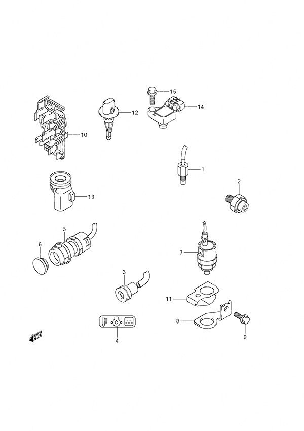
Fig. 22 - Sensor/Switch для Suzuki DF 20A - 2013 года выпуска
-
№АртикулНазвание
-
113640-32G01-000 Engine Temp SensorEngine Temp Sensor
-
237820-93E11-000 Oil Pressure SwitchOil Pressure Switch
-
336360-99J10-000 Oil Pressure IndicatorOil Pressure Indicator
-
436367-89L00-000 Warning LabelWarning Label
-
537161-89L02-000 Starter Motor Switch Assembly
w/Electric StarterStarter Motor Switch Assembly
w/Electric Starter -
637163-89L00-000 Starting Switch Hole Plug
w/Manual StarterStarting Switch Hole Plug
w/Manual Starter -
737721-89L00-000 Neutral Switch AssemblyNeutral Switch Assembly
-
837726-89L00-000 Neutral Switch Bracket (NLA)Neutral Switch Bracket (NLA)
-
901550-06167-000 Bolt (6x16)Bolt (6x16)
-
1036616-89L00-000 Connector Holder (NLA)Connector Holder (NLA)
-
1137725-89L01-000 Neutral Switch ActuatorNeutral Switch Actuator
-
1213650-52G00-000 Inlet Air Temp SensorInlet Air Temp Sensor
-
1313655-89L00-000 Air Temp Sensor GrommetAir Temp Sensor Grommet
-
1418590-58M00-000 MAP SensorMAP Sensor
-
1501550-06207-000 Bolt (6x20)Bolt (6x20)
Все узлы модели:
-
Fig. 1 - Cylinder Head
S/N 02002F-310001 to 02002F-31XXXX -
Fig. 2 - Cylinder Block
S/N 02002F-310001 to 02002F-31XXXX -
Fig. 3 - Crankshaft
S/N 02002F-310001 to 02002F-31XXXX -
Fig. 5 - Camshaft
S/N 02002F-310001 to 02002F-31XXXX -
Fig. 4 - Timing Belt
S/N 02002F-310001 to 02002F-31XXXX -
Fig. 7 - Inlet Manifold
S/N 02002F-310001 to 02002F-31XXXX -
Fig. 8 - Fuel Injector
S/N 02002F-310001 to 02002F-31XXXX -
Fig. 9 - Fuel Pump
S/N 02002F-310001 to 02002F-31XXXX -
Fig. 10 - Water Pump
S/N 02002F-310001 to 02002F-31XXXX -
Fig. 11 - Thermostat
S/N 02002F-310001 to 02002F-31XXXX -
Fig. 12 - Recoil Starter
S/N 02002F-310001 to 02002F-31XXXX -
Fig. 13 - Throttle Body
S/N 02002F-310001 to 02002F-31XXXX -
Fig. 14 - Oil Pump
S/N 02002F-310001 to 02002F-31XXXX -
Fig. 15 - Clutch Rod
S/N 02002F-310001 to 02002F-31XXXX -
Fig. 16 - Shift Rod
S/N 02002F-310001 to 02002F-31XXXX -
Fig. 17 - Transmission
S/N 02002F-310001 to 02002F-31XXXX -
Fig. 18 - Starter Motor Electric Starter
S/N 02002F-310001 to 02002F-31XXXX -
Fig. 19 - Magneto
S/N 02002F-310001 to 02002F-31XXXX -
Fig. 21 - Rectifier/Ignition Coil
S/N 02002F-310001 to 02002F-31XXXX - • Fig. 22 - Sensor/Switch
S/N 02002F-310001 to 02002F-31XXXX -
Fig. 28 - Gear Case
S/N 02002F-310001 to 02002F-31XXXX -
Fig. 29 - Side Cover
S/N 02002F-310001 to 02002F-31XXXX -
Fig. 31 - Engine Cover
S/N 02002F-310001 to 02002F-31XXXX -
Fig. 32 - Tiller Handle
S/N 02002F-310001 to 02002F-31XXXX -
Fig. 33 - Fuel Tank
S/N 02002F-310001 to 02002F-31XXXX -
Fig. 34 - Opt: Electrical Manual Starter
S/N 02002F-310001 to 02002F-31XXXX -
Fig. 36 - Opt: Starting Motor Manual Starter
S/N 02002F-310001 to 02002F-31XXXX -
Fig 40 - Opt: Top Mount Single (2)
S/N 02002F-310001 to 02002F-31XXXX -
Fig 39 - Opt: Top Mount Single (1)
S/N 02002F-310001 to 02002F-31XXXX -
Fig. 41 - Opt: Remote Control
S/N 02002F-310001 to 02002F-31XXXX -
Fig. 42 - Opt: Remocon Cable Electric Starter
S/N 02002F-310001 to 02002F-31XXXX -
Fig. 43 - Opt: Drag Link
S/N 02002F-310001 to 02002F-31XXXX -
Fig. 23 - Harness
S/N 02002F-310001 to 02002F-31XXXX -
Fig. 24 - Clamp Bracket
S/N 02002F-310001 to 02002F-31XXXX -
Fig. 25 - Swivel Bracket
S/N 02002F-310001 to 02002F-31XXXX -
Fig. 26 - Engine Holder
S/N 02002F-310001 to 02002F-31XXXX -
Fig. 27 - Drive Shaft Housing
S/N 02002F-310001 to 02002F-31XXXX -
Fig. 38 - Opt: Remote Control Parts
S/N 02002F-310001 to 02002F-31XXXX -
Fig. 37 - Opt: Fuel Tank
S/N 02002F-310001 to 02002F-31XXXX