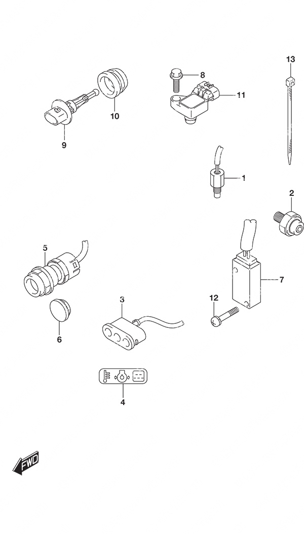
Fig. 334A - Sensor/Switch для Suzuki DF 25A - 2016 года выпуска

-
№АртикулНазвание
-
113640-32G20-000 Engine Temp SensorEngine Temp Sensor
-
237820-80002-000 Oil Pressure Switch AssemblyOil Pressure Switch Assembly
-
336360-94L00-000 Warning IndicatorWarning Indicator
-
436367-89L00-000 Warning LabelWarning Label
-
537161-89L02-000 Starter Motor Switch Assembly
w/Electric StarterStarter Motor Switch Assembly
w/Electric Starter -
637163-89L00-000 Starting Switch Hole Plug
w/Manual StarterStarting Switch Hole Plug
w/Manual Starter -
737721-94L00-000 Neutral Switch AssemblyNeutral Switch Assembly
-
801550-06207-000 Bolt (6x20)Bolt (6x20)
-
913650-52G00-000 Inlet Air Temp SensorInlet Air Temp Sensor
-
1013655-87J00-000 Air Temp Sensor GrommetAir Temp Sensor Grommet
-
1118590-58M00-000 MAP SensorMAP Sensor
-
1209137-03008-000 Screw (3x18)Screw (3x18)
-
1309407-14407-000 Clamp (L:145)Clamp (L:145)
Все узлы модели:
-
Fig. 111 - Cylinder Head
S/N 02504F-610001 to 02504F-61XXXX -
Fig. 113 - Cylinder Block
S/N 02504F-610001 to 02504F-61XXXX -
Fig. 116 - Crankshaft
S/N 02504F-610001 to 02504F-61XXXX -
Fig. 120 - Timing Belt
S/N 02504F-610001 to 02504F-61XXXX -
Fig. 121 - Camshaft
S/N 02504F-610001 to 02504F-61XXXX -
Fig. 122 - Intake Manifold
S/N 02504F-610001 to 02504F-61XXXX -
Fig. 139 - Exhaust Manifold
S/N 02504F-610001 to 02504F-61XXXX -
Fig. 144 - Fuel Injector
S/N 02504F-610001 to 02504F-61XXXX -
Fig. 146 - Fuel Pump
S/N 02504F-610001 to 02504F-61XXXX -
Fig. 160 - Water Pump
S/N 02504F-610001 to 02504F-61XXXX -
Fig. 162 - Thermostat
S/N 02504F-610001 to 02504F-61XXXX -
Fig. 163 - Throttle Body
S/N 02504F-610001 to 02504F-61XXXX -
Fig. 166A - Throttle Control
S/N 02504F-610001 to 02504F-61XXXX -
Fig. 166B - Throttle Control Remote Control
S/N 02504F-610001 to 02504F-61XXXX -
Fig. 167 - Recoil Starter
S/N 02504F-610001 to 02504F-61XXXX -
Fig. 175 - Oil Pump
S/N 02504F-610001 to 02504F-61XXXX -
Fig. 206A - Clutch Rod
S/N 02504F-610001 to 02504F-61XXXX -
Fig. 220 - Transmission
S/N 02504F-610001 to 02504F-61XXXX -
Fig. 301 - Starting Motor
S/N 02504F-610001 to 02504F-61XXXX -
Fig. 303A - Magneto Manual Starter
S/N 02504F-610001 to 02504F-61XXXX -
Fig. 303B - Magneto Electric Starter
S/N 02504F-610001 to 02504F-61XXXX -
Fig. 310 - Rectifier/Ignition Coil
S/N 02504F-610001 to 02504F-61XXXX -
Fig. 322A - Harness
S/N 02504F-610001 to 02504F-61XXXX -
Fig. 322B - Harness Remote Control
S/N 02504F-610001 to 02504F-61XXXX -
Fig. 322C - Harness Tiller Handle w/Power Tilt
S/N 02504F-610001 to 02504F-61XXXX -
Fig. 327A - PTT Switch Remote Control w/Power Tilt
S/N 02504F-610001 to 02504F-61XXXX -
Fig. 327B - PTT Switch Tiller Handle w/Power Tilt
S/N 02504F-610001 to 02504F-61XXXX - • Fig. 334A - Sensor/Switch
S/N 02504F-610001 to 02504F-61XXXX -
Fig. 334B - Sensor/Switch Remote Control
S/N 02504F-610001 to 02504F-61XXXX -
Fig. 334C - Sensor/Switch Tiller Handle w/Power Tilt
S/N 02504F-610001 to 02504F-61XXXX -
Fig. 335A - Clamp Bracket
S/N 02504F-610001 to 02504F-61XXXX -
Fig. 335B - Clamp Bracket w/Power Tilt
S/N 02504F-610001 to 02504F-61XXXX -
Fig. 336A - Swivel Bracket
S/N 02504F-610001 to 02504F-61XXXX -
Fig. 336B - Swivel Bracket Remote Control
S/N 02504F-610001 to 02504F-61XXXX -
Fig. 336C - Swivel Bracket Remote Control w/Power Tilt
S/N 02504F-610001 to 02504F-61XXXX -
Fig. 336D - Swivel Bracket Tiller Handle w/Power Tilt
S/N 02504F-610001 to 02504F-61XXXX -
Fig. 338 - Tilt Cylinder
S/N 02504F-610001 to 02504F-61XXXX -
Fig. 340 - PTT Motor
S/N 02504F-610001 to 02504F-61XXXX -
Fig. 401 - Engine Holder
S/N 02504F-610001 to 02504F-61XXXX -
Fig. 405 - Drive Shaft Housing
S/N 02504F-610001 to 02504F-61XXXX -
Fig. 407 - Gear Case
S/N 02504F-610001 to 02504F-61XXXX -
Fig. 410A - Side Cover
S/N 02504F-610001 to 02504F-61XXXX -
Fig. 410C - Side Cover Remote Control w/Power Tilt
S/N 02504F-610001 to 02504F-61XXXX -
Fig. 410D - Side Cover Tiller Handle w/Power Tilt
S/N 02504F-610001 to 02504F-61XXXX -
Fig. 442 - Drag link
S/N 02504F-610001 to 02504F-61XXXX -
Fig. 444 - Tiller Handle
S/N 02504F-610001 to 02504F-61XXXX -
Fig. 450A - Remote Control
S/N 02504F-610001 to 02504F-61XXXX -
Fig. 450B - Remote Control w/Power Tilt
S/N 02504F-610001 to 02504F-61XXXX -
Fig. 501 - Opt: Meter
S/N 02504F-610001 to 02504F-61XXXX -
Fig. 517 - Opt: Concealed Remocon (1)
S/N 02504F-610001 to 02504F-61XXXX -
Fig. 518 - Opt: Concealed Remocon (2)
S/N 02504F-610001 to 02504F-61XXXX -
Fig. 530 - Opt: Switch
S/N 02504F-610001 to 02504F-61XXXX -
Fig. 544 - Opt: Top Mount Single (1)
S/N 02504F-610001 to 02504F-61XXXX -
Fig. 545 - Opt: Top Mount Single (2)
S/N 02504F-610001 to 02504F-61XXXX -
Fig. 553 - Opt: Electrical Manual Starter
S/N 02504F-610001 to 02504F-61XXXX -
Fig. 561 - Opt: Starting Motor Manual Starter
S/N 02504F-610001 to 02504F-61XXXX -
Fig. 206B - Clutch Rod Remote Control
S/N 02504F-610001 to 02504F-61XXXX -
Fig. 210 - Shift Rod
S/N 02504F-610001 to 02504F-61XXXX -
Fig. 410B - Side Cover Remote Control
S/N 02504F-610001 to 02504F-61XXXX -
Fig. 420 - Engine Cover
S/N 02504F-610001 to 02504F-61XXXX -
Fig. 432 - Fuel Tank
S/N 02504F-610001 to 02504F-61XXXX -
Fig. 513A - Opt: Remote Control Parts
S/N 02504F-610001 to 02504F-61XXXX -
Fig. 513B - Opt: Remote Control Parts Tiller Handle w/Power Tilt
S/N 02504F-610001 to 02504F-61XXXX